Physical Layer: Ethernet | Ethernet Physical Layer And Modern Networking
Category: NETWORKING | 18th August 2026, Tuesday
1. Introduction
Ethernet Is One Of The Most Widely Deployed Technologies For Computer Networking And Forms A Fundamental Part Of Modern Local Area Networks (LANs). Although Ethernet Is Commonly Discussed As A Data Link Layer Technology, Its Operation Extends Into The Physical Layer, Where It Defines How Binary Information Is Converted Into Electrical, Optical, Or Radio-frequency Signals And Transmitted Through A Physical Medium. At The Postgraduate Level, Understanding Ethernet Therefore Requires Examining Not Only Frames And MAC Addresses But Also Signaling, Transmission Media, Encoding, Modulation, Synchronization, Bandwidth, Duplex Operation, Standards, And The Relationship Between The Physical Layer And Higher Networking Layers.
Ethernet Originated From Research At Xerox PARC In The 1970s And Was Subsequently Standardized Through The Work Of The IEEE 802.3 Ethernet Working Group. Over Several Decades, Ethernet Has Evolved From A 10 Mbps Shared-medium Technology Into A Family Of Standards Supporting Speeds Ranging From Traditional Megabit Networks To 10 Gbps, 25 Gbps, 40 Gbps, 100 Gbps, 200 Gbps, 400 Gbps, 800 Gbps And Beyond In Specialized Data-center And Backbone Environments. Despite These Dramatic Changes In Speed And Physical Implementation, The Fundamental Objective Remains The Same: Reliably Transporting Digital Information Over A Physical Communication Medium.
At The Physical Layer, Ethernet Is Concerned With The Transmission And Reception Of Raw Bit Streams. It Specifies Characteristics Such As Cable Type, Connector/interface, Signal Levels, Wavelengths, Frequencies, Transmission Distances, Encoding Mechanisms, Clock Recovery, And Signaling Techniques. The Physical Layer Does Not Generally Interpret The Semantic Meaning Of The Data. Instead, It Provides The Mechanism By Which A Sequence Of Bits Can Physically Travel From One Network Interface To Another.
2. Ethernet And The OSI Physical Layer
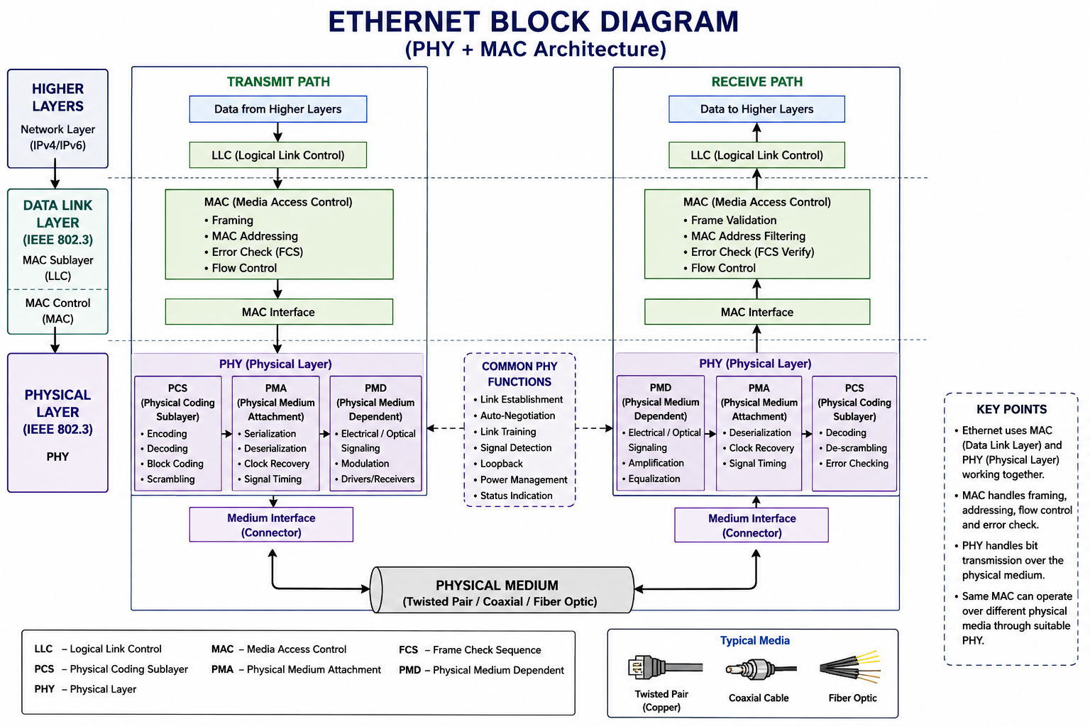
The OSI Reference Model Divides Communication Functions Into Seven Layers. Ethernet Primarily Operates At The Data Link Layer (Layer 2) And Physical Layer (Layer 1). The Data Link Layer Is Responsible For Ethernet Frame Formation, Media Access Control (MAC), Addressing, Frame Validation, And Related Functions. The Physical Layer Is Responsible For Transmitting The Resulting Bit Stream Across The Medium.
A Useful Conceptual Representation Is:
Application Data → Network Packet → Ethernet Frame → Bit Stream → Physical Signal → Transmission Medium
At The Transmitting Host, Data Generated By An Application Eventually Becomes An Ethernet Frame. The Physical Layer Receives The Encoded Bit Stream From The Ethernet MAC/PHY Interface And Transforms It Into An Appropriate Physical Signal. At The Receiving End, The PHY Detects The Incoming Signal, Recovers Timing, Decodes The Physical Representation, And Reconstructs The Bit Stream For Delivery To The MAC Layer.
This Separation Is Important Because The Same Ethernet Framing Architecture Can Operate Over Significantly Different Physical Technologies. For Example, Ethernet May Use Twisted-pair Copper, Multimode Fiber, Single-mode Fiber, Or Other Specialized Physical Media Depending On The IEEE Standard.
3. Ethernet Physical-Layer Architecture
A Modern Ethernet Implementation Can Be Understood Through Several Functional Components. The MAC (Media Access Control) Operates Primarily At Layer 2, While The PHY (Physical Layer Device) Performs Layer 1 Functions. The PHY Commonly Includes A Transmitter, Receiver, Encoding/decoding Functions, Clock Recovery, Signal Conditioning, And Medium-specific Interfaces.
A Simplified Architecture Is:
MAC → PCS → PMA → PMD → Medium
Here, The Physical Coding Sublayer (PCS) Performs Functions Such As Encoding, Decoding, Synchronization, And Data Transformation. The Physical Medium Attachment (PMA) Provides Functions Related To Serialization, Deserialization, Clock Recovery, And Physical Signal Processing. The Physical Medium Dependent (PMD) Defines Characteristics Specific To The Transmission Medium, Including Optical Or Electrical Signaling.
The Exact Organization Varies Among Ethernet Generations And Physical Standards, But The Conceptual Separation Allows Ethernet To Support Many Physical Media While Maintaining A Common Higher-level Architecture.
4. Ethernet Transmission Media
Ethernet Has Historically Operated Over Several Types Of Physical Media. The Major Categories Are twisted-pair Copper, Coaxial Cable, And Optical Fiber.
Twisted-Pair Ethernet
Twisted-pair Ethernet Is Extensively Used In Office Networks, Educational Institutions, Homes, And Enterprise Environments. Common Categories Include Cat5e, Cat6, Cat6A, And Higher-performance Cabling Systems.
Twisted-pair Cables Contain Pairs Of Insulated Copper Conductors Twisted Together. Twisting Reduces Electromagnetic Interference And Crosstalk. Ethernet Systems Use Differential Signaling, In Which Information Is Represented By The Voltage Difference Between Conductors Rather Than By An Absolute Voltage Relative To Ground.
Standards Such As 100BASE-TX, 1000BASE-T, And 10GBASE-T Demonstrate The Increasing Sophistication Of Copper Ethernet. Gigabit Ethernet, For Example, Uses All Four Twisted Pairs And Advanced Signal-processing Techniques To Achieve High Data Rates Over Copper.
Coaxial Ethernet
Early Ethernet Technologies Such As 10BASE5 And 10BASE2 Used Coaxial Cable. These Systems Were Based On Shared Physical Media And Were Associated With The Original Ethernet Bus Architecture. Coaxial Ethernet Is Now Largely Obsolete In Modern LAN Deployments Because Switched Twisted-pair And Fiber Ethernet Provide Greater Scalability, Flexibility, And Performance.
Fiber-Optic Ethernet
Fiber Ethernet Transmits Information Using Pulses Or Modulated Patterns Of Light. Fiber Provides Significant Advantages In Terms Of Bandwidth, Electromagnetic Immunity, Transmission Distance, And Security Against Certain Forms Of Electromagnetic Interference.
Two Important Fiber Categories Are multimode Fiber (MMF) And single-mode Fiber (SMF). Multimode Fiber Generally Supports Shorter Distances And Is Widely Used Within Buildings And Data Centers. Single-mode Fiber Supports Much Longer Distances And Is Extensively Used In Campus, Metropolitan, Carrier, And Data-center Interconnection Environments.
5. Ethernet Naming Convention
Ethernet Physical Standards Traditionally Use Names Such As 10BASE-T, 100BASE-TX, 1000BASE-T, 10GBASE-SR, And 10GBASE-LR.
The Notation Can Communicate Several Characteristics.
For Example:
1000BASE-T
-
1000 Indicates A Nominal Data Rate Of 1000 Mbps.
-
BASE Indicates Baseband Transmission.
-
T Identifies Twisted-pair Copper As The Physical Medium.
Similarly:
10GBASE-SR
-
10G Represents 10 Gbps.
-
BASE Represents Baseband Transmission.
-
SR Refers To Short-range Optical Transmission, Generally Associated With Multimode Fiber.
The Naming Conventions Provide A Convenient Way Of Identifying The Physical Characteristics Of Ethernet Implementations.
6. Signal Encoding And Physical Signaling
One Of The Most Important Physical Layer Concepts Is The Conversion Of Digital Bits Into Physical Signals. A Computer Internally Represents Information Using Binary Values, But A Physical Communication Channel Does Not Directly Transmit Abstract 0s And 1s. Instead, Bits Must Be Represented Using Changes In Voltage, Current, Light Intensity, Phase, Frequency, Or Other Physical Properties.
Different Ethernet Generations Employ Different Signaling Mechanisms.
Early Ethernet Technologies Used Techniques Such As Manchester Encoding, Where Signal Transitions Provide Both Data Representation And Clock Synchronization. Manchester Encoding Has The Advantage Of Facilitating Synchronization But Requires More Physical Bandwidth Than More Efficient Encoding Schemes.
Fast Ethernet Introduced Techniques Such As 4B/5B Encoding, Which Maps Groups Of Four Data Bits Into Five-bit Symbols. Gigabit Ethernet And Later Technologies Employ Progressively More Sophisticated Coding And Modulation Methods.
At Higher Data Rates, Ethernet Physical Layers May Use Techniques Involving Multiple Signal Levels, Sophisticated Forward Error Correction, Digital Signal Processing, And Parallel Or Multi-lane Transmission. Consequently, Modern Ethernet PHYs Are Highly Complex Systems Rather Than Simple Electrical Transmitters.
7. Bandwidth, Data Rate, And Symbol Rate
A Common Misconception Is That Ethernet Speed Is Always Identical To The Physical Signaling Rate. At The Physical Layer, These Concepts Must Be Distinguished.
Bit Rate Represents The Number Of Bits Transmitted Per Second, Whereas symbol Rate Represents The Number Of Signal Symbols Transmitted Per Second. If A Single Symbol Can Represent Multiple Bits, The Bit Rate Can Exceed The Symbol Rate.
Physical-layer Overhead Can Also Mean That The Raw Signaling Rate Is Higher Than The Useful Payload Rate. Encoding, Synchronization Information, Error Correction, Framing, And Other Mechanisms May Consume Part Of The Available Transmission Capacity.
This Distinction Becomes Increasingly Important In High-speed Ethernet, Where Multi-level Signaling, Multiple Lanes, Encoding Schemes, And Forward Error Correction Are Used To Achieve Extremely High Aggregate Data Rates.
8. Duplex Operation
Ethernet Can Operate Using half-duplex Or full-duplex Communication.
In Half-duplex Ethernet, Devices Share The Same Communication Medium And Cannot Transmit And Receive Simultaneously. Classical Shared Ethernet Used Carrier Sense Multiple Access With Collision Detection (CSMA/CD) To Manage Access To The Shared Medium.
In Full-duplex Ethernet, A Device Can Transmit And Receive Simultaneously. Modern Switched Ethernet Networks Overwhelmingly Use Full-duplex Communication. Because Each Point-to-point Link Has Independent Transmission And Reception Paths, Collisions Are Eliminated, Making CSMA/CD Unnecessary In Normal Full-duplex Operation.
This Transition From Shared-medium Ethernet To Switched Full-duplex Ethernet Was One Of The Most Important Architectural Developments In Ethernet History.
9. Physical-Layer Synchronization
Reliable High-speed Communication Requires The Receiver To Determine Where Individual Bits Or Symbols Occur In The Incoming Signal. This Requires clock Recovery And Synchronization.
A Receiver Cannot Simply Assume That Its Local Clock Is Perfectly Synchronized With The Transmitter. Differences In Oscillator Frequency, Propagation Delay, Signal Distortion, And Noise Can Cause Timing Errors.
Ethernet PHY Implementations Therefore Employ Synchronization Mechanisms That Allow The Receiver To Recover Timing Information From The Received Signal. At Very High Speeds, Clock-data Recovery Becomes A Sophisticated Signal-processing Problem.
Poor Synchronization Can Lead To Bit Errors, Loss Of Frame Integrity, And Communication Failures.
10. Signal Attenuation And Dispersion
Physical Transmission Media Are Not Ideal. Signals Become Weaker As They Travel Through A Medium. This Phenomenon Is Called attenuation.
Copper Cables Experience Attenuation Due To Conductor Resistance, Dielectric Losses, And Frequency-dependent Effects. Fiber-optic Systems Experience Optical Attenuation Caused By Absorption, Scattering, Connector Losses, And Other Physical Mechanisms.
Another Important Phenomenon Is dispersion, Where Different Components Of A Transmitted Signal Propagate Differently Through The Medium. Dispersion Can Cause Pulse Spreading And Inter-symbol Interference.
At Higher Data Rates And Longer Distances, Attenuation And Dispersion Become Increasingly Significant. Ethernet PHY Designs Therefore Employ Equalization, Amplification, Signal Conditioning, And Other Techniques To Compensate For Physical-channel Impairments.
11. Electromagnetic Interference And Crosstalk
Copper Ethernet Is Susceptible To Electromagnetic Interference (EMI) And Crosstalk. EMI Can Originate From Electrical Equipment, Motors, Radio Transmitters, Power Systems, And Other Sources.
Crosstalk Occurs When Signals Traveling Through One Conductor Pair Interfere With Signals On Another Pair. Near-End Crosstalk (NEXT) And Far-End Crosstalk (FEXT) Are Important Parameters In High-speed Twisted-pair Ethernet.
Cable Construction, Shielding, Twisting Geometry, Connector Design, And Signal-processing Algorithms Are Used To Reduce These Effects.
Fiber-optic Ethernet Is Largely Immune To Electromagnetic Interference Because Information Is Transmitted Using Light Rather Than Electrical Current. This Makes Fiber Particularly Attractive For Industrial Environments, Long-distance Links, And Electrically Noisy Locations.
12. Auto-Negotiation
Modern Ethernet Interfaces Often Support auto-negotiation, Enabling Connected Devices To Determine Compatible Operating Parameters.
Depending On The Ethernet Technology, Parameters May Include Supported Speed, Duplex Mode, And Other Capabilities. Auto-negotiation Simplifies Network Deployment Because Administrators Do Not Necessarily Need To Manually Configure Both Endpoints.
However, Mismatched Configurations Can Cause Performance Problems. For Example, An Incorrectly Configured Interface May Create Duplex Mismatches Or Prevent Successful Link Establishment.
13. Ethernet Link Establishment
Before Normal Data Communication Begins, Ethernet Devices Must Establish A Physical Link.
The PHY Detects Electrical Or Optical Characteristics On The Medium And Determines Whether The Remote Device Is Present And Operating Compatibly. Depending On The Ethernet Standard, Link Establishment Can Involve Signaling Sequences, Training Procedures, Auto-negotiation, Clock Synchronization, And Equalization.
Modern High-speed Copper Links May Perform Substantial Channel Training Before Becoming Operational. The PHY Evaluates The Quality Of The Communication Channel And Adjusts Parameters To Compensate For Channel Characteristics.
Therefore, The Apparently Simple Concept Of An Ethernet Cable Being "connected" Actually Involves Sophisticated Physical-layer Processes.
14. Error Detection And Physical Reliability
Ethernet Frame Integrity Is Primarily Associated With Layer 2 Through Mechanisms Such As The Frame Check Sequence (FCS). However, The Physical Layer Also Incorporates Mechanisms Intended To Improve Signal Reliability.
Modern High-speed Ethernet Can Employ Forward Error Correction (FEC), Particularly Where Extremely High Data Rates Make Raw Physical Transmission More Susceptible To Errors.
FEC Introduces Redundant Information That Allows The Receiver To Detect And Correct Certain Classes Of Transmission Errors Without Requiring Retransmission. This Is Especially Valuable In High-speed Data-center And Optical Communication Systems.
The Interaction Between Physical-layer Error Correction And Higher-layer Protocols Demonstrates That Reliable Networking Is Achieved Through Cooperation Among Multiple Protocol Layers.
15. Ethernet Evolution
Ethernet Has Evolved Through Several Major Performance Generations:
-
10 Mbps Ethernet — Early Standardized Ethernet.
-
100 Mbps Fast Ethernet — Substantially Increased LAN Performance.
-
1 Gbps Gigabit Ethernet — Became A Mainstream Enterprise LAN Technology.
-
10 Gbps Ethernet — Widely Adopted In Server, Data-center, And Backbone Networks.
-
25/40 Gbps Ethernet — Important In Modern Data Centers.
-
50/100 Gbps Ethernet — Increasingly Common For High-performance Infrastructure.
-
200/400/800 Gbps Ethernet — Used In Advanced Data-center, Cloud, And High-capacity Networking Environments.
The Evolution Demonstrates A Central Principle Of Networking Engineering: The Logical Ethernet Architecture Can Remain Relatively Stable While The Physical Layer Undergoes Substantial Technological Change.
16. Ethernet In Data Centers
Modern Data Centers Place Enormous Demands On Ethernet. Cloud Computing, Artificial Intelligence, Virtualization, Distributed Databases, Storage Systems, And High-performance Computing Require Extremely High Bandwidth And Low Latency.
Data-center Ethernet Increasingly Uses High-speed Optical Interfaces And Multiple Parallel Lanes. Instead Of Transmitting An Entire High-speed Data Stream Through One Physical Channel, Data Can Be Distributed Across Multiple Lanes And Reconstructed At The Receiving Endpoint.
This Approach Enables Scalable Aggregate Bandwidth While Allowing Improvements In Optical And Electrical Components To Occur Independently.
17. Ethernet And Power Over Ethernet
An Important Extension Of Twisted-pair Ethernet Is Power Over Ethernet (PoE). PoE Allows Electrical Power And Network Communication To Be Delivered Over Ethernet Cabling.
PoE Is Widely Used For Devices Such As Wireless Access Points, IP Cameras, VoIP Phones, Sensors, And Other Network-connected Equipment.
From A Physical-layer Perspective, PoE Demonstrates That Ethernet Cabling Can Support Both Data Transmission And Power Delivery When Appropriate Standards And Equipment Are Used. The Electrical Characteristics Of The Cable And Connected Devices Must Be Carefully Controlled To Maintain Safety And Reliable Communication.
18. Physical-Layer Performance Parameters
Several Parameters Are Important When Evaluating Ethernet Physical Layer Performance:
-
Data Rate — Number Of Transmitted Bits Per Second.
-
Bandwidth — Frequency Range Supported By The Physical Channel.
-
Transmission Distance — Maximum Supported Link Length Under Specified Conditions.
-
Bit Error Rate (BER) — Probability Or Frequency Of Bit Transmission Errors.
-
Latency — Time Required For Signals To Propagate And Processing To Occur.
-
Signal-to-Noise Ratio (SNR) — Relationship Between Useful Signal Power And Noise.
-
Attenuation — Reduction In Signal Strength.
-
Crosstalk — Interference Between Neighboring Channels.
-
Jitter — Deviation Of Signal Transitions From Their Ideal Timing Positions.
-
Return Loss — Signal Reflection Caused By Impedance Discontinuities.
These Parameters Are Essential In Designing, Deploying, And Troubleshooting Ethernet Networks.
19. Ethernet And Network Topology
Classical Ethernet Used A Bus Topology In Which Multiple Devices Shared A Common Physical Medium. Modern Ethernet Generally Uses A star Or Extended-star Topology, Where End Devices Connect To Switches.
The Switch Creates Individual Point-to-point Links Between Devices And The Switching Infrastructure. This Architecture Improves Scalability, Reduces Collisions, Enables Full-duplex Communication, And Simplifies Network Management.
At The Physical Layer, The Topology Determines Cable Paths, Link Lengths, Connector Arrangements, Transceiver Requirements, And Physical Redundancy.
20. Ethernet Physical Layer And Modern Networking
The Importance Of Ethernet Extends Beyond Traditional LANs. Ethernet Is Now Fundamental To Enterprise Networks, Cloud Computing, Industrial Networks, Telecommunications, Internet Exchange Points, Data Centers, Storage Networks, And High-performance Computing Environments.
Its Success Can Be Attributed To Several Characteristics: Standardization, Interoperability, Scalability, Relatively Low Cost, Extensive Vendor Support, Backward Compatibility, And Continuous Evolution.
The Physical Layer Has Played A Particularly Important Role In This Evolution. Innovations In Optical Transceivers, Copper Signaling, Semiconductor Technology, Digital Signal Processing, Error Correction, And Photonics Have Enabled Ethernet To Scale From Megabit Communication To Hundreds Of Gigabits Per Second And Beyond.
21. Advanced PG-Level Perspective
At The Postgraduate Level, Ethernet Physical Layer Should Not Be Viewed Simply As A Mechanism For Sending 0s And 1s Through A Cable. It Is An Interdisciplinary Engineering System Involving digital Communications, Electromagnetic Theory, Signal Processing, Semiconductor Electronics, Coding Theory, Information Theory, And Network Architecture.
For Example, Increasing Ethernet Speed Requires Consideration Of Shannon-style Channel Limitations, Signal-to-noise Ratios, Bandwidth Efficiency, Channel Distortion, Power Consumption, Thermal Constraints, And Implementation Complexity. Higher Data Rates Often Require Increasingly Sophisticated Modulation, Equalization, Coding, And Error-correction Mechanisms.
Consequently, Ethernet's Development Illustrates A Broader Networking Principle: Improving Network Capacity Is Not Merely A Matter Of Increasing Clock Frequency. It Requires Coordinated Advances In Physical Media, Transceiver Technology, Coding, Signal Processing, Architecture, And Standards.
22. Conclusion
Ethernet At The Physical Layer Provides The Foundation Through Which Digital Information Becomes A Physical Signal Capable Of Traveling Across A Communication Medium. It Defines Essential Characteristics Such As Transmission Media, Signaling, Encoding, Synchronization, Data Rates, Link Distances, Electrical And Optical Interfaces, And Physical Reliability.
From Early 10 Mbps Coaxial Networks To Today's Multi-hundred-gigabit Optical And Electrical Systems, Ethernet Has Continuously Evolved While Preserving A Highly Interoperable Networking Framework. The Transition From Shared Half-duplex Media To Switched Full-duplex Networks, The Development Of Twisted-pair And Fiber-optic Technologies, The Adoption Of Advanced Coding And Modulation, And The Use Of FEC And Digital Signal Processing Have Transformed Ethernet Into A Highly Sophisticated Communication Technology.
For Postgraduate Computer Science And Networking Studies, Ethernet Should Therefore Be Understood As Both A protocol Family And A Physical Communication Ecosystem. Its Physical Layer Represents The Critical Boundary Between Abstract Digital Information And Real-world Communication Phenomena. Understanding This Layer Provides A Foundation For Advanced Study Of Network Architecture, High-speed Communications, Data-center Networking, Optical Networking, Network Performance Engineering, And Emerging Technologies Such As Terabit-scale Ethernet.
Tags:
Ethernet, Physical Layer, Modern Networking, Digital Communications, Electromagnetic Theory, Signal Processing, Semiconductor Electronics, Coding Theory, Information Theory, And Network Architecture.