Physical Layer: RS-232 | RS-232 And The OSI Physical Layer | RS-232 And The Physical Layer
Category: NETWORKING | 18th August 2026, Tuesday
1. Introduction
RS-232 Is One Of The Most Historically Important Standards For Serial Communication Between Computers, Terminals, Modems, And Other Electronic Devices. It Defines The Electrical, Functional, And Mechanical Characteristics Required For Exchanging Serial Binary Data Between Two Devices. Although Modern Interfaces Such As USB, Ethernet, RS-422, And RS-485 Have Replaced RS-232 In Many Applications, RS-232 Remains Highly Relevant In Industrial Automation, Embedded Systems, Laboratory Instruments, Networking Equipment, CNC Machines, Serial Consoles, And Legacy Computer Systems.
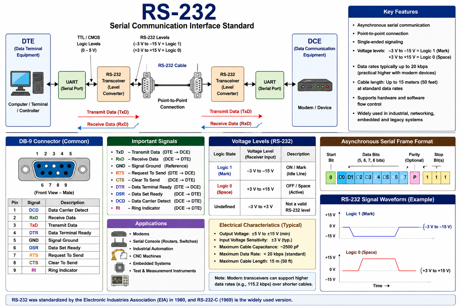
From A Networking Perspective, RS-232 Is Primarily Associated With The Physical Layer Because It Specifies How Binary Information Is Represented Electrically On An Interface. It Defines Voltage Levels, Signal Timing, Electrical Characteristics, Connector Arrangements, And The Functions Of Interface Circuits. The Standard Does Not Itself Define Higher-level Application Protocols Or A Particular Character Encoding Such As ASCII. Those Functions Are Normally Provided By UARTs, Software, And Higher-level Protocols.
RS-232 Was Developed To Solve An Important Problem In Early Computer Communications: Different Manufacturers Used Incompatible Electrical Interfaces For Connecting Data Terminal Equipment (DTE) To Data Communication Equipment (DCE). A Common Standard Was Needed So That Equipment From Different Manufacturers Could Communicate Reliably. The Electronic Industries Association (EIA) Developed The Standard, Initially Publishing RS-232 In May 1960. It Subsequently Went Through Revisions, Including RS-232-A In 1963, RS-232-B In 1965, And The Particularly Influential RS-232-C In August 1969. Historical U.S. Government Documentation Identifies The EIA Subcommittee TR-30.2 As The Maintenance Authority For RS-232-C.
2. Who Invented RS-232?
A Common Question Is: "Who Invented RS-232?"
Strictly Speaking, RS-232 Was not Invented By A Single Individual. It Was Developed As An industry Standard By The Electronic Industries Association (EIA) Through A Standards Committee Concerned With Data-terminal And Communications Equipment Interfaces. Therefore, Attributing RS-232 To One Inventor Would Be Historically Inaccurate.
The Original Motivation Was The Need For A Standardized Interface Between data Terminal Equipment And Data Communication Equipment, Particularly Terminals Or Computers Connected To Modems. At That Time, Digital Computers And Electromechanical Terminals Frequently Communicated Over Telephone Networks Using Modems. Different Manufacturers Could Implement Different Electrical Signaling Arrangements, Making Interoperability Difficult. The EIA's Standardization Effort Provided Common Electrical And Interface Specifications.
The First RS-232 Standard Dates To 1960, While RS-232-C, Published In 1969, Became The Version Most Strongly Associated With The Widespread Adoption Of The Interface. The Standard Was Later Revised And Renamed Through Changes In The Organizations Responsible For Telecommunications Standards. Modern References Commonly Use Names Such As EIA-232, ANSI/TIA/EIA-232, And TIA-232.
Thus, For Academic Purposes, The Correct Statement Is:
RS-232 Was Developed And Standardized By The Electronic Industries Association (EIA), Beginning In 1960; It Was Not The Invention Of A Single Person.
3. Historical Background
During The Early Development Of Computer Communications, Computers Were Often Large Centralized Systems. Users Interacted With These Systems Through Terminals, Including Teleprinters And Other Electromechanical Devices. Communication Over Long Distances Frequently Required Modems Connected Through Telephone Lines.
The Basic Communication Arrangement Was:
Computer/Terminal → DTE → RS-232 Interface → DCE/Modem → Telephone Network
The DTE Represented The Device That Generated Or Consumed Data, While The DCE Generally Provided Communication-channel Access Or Signal Conversion. A Modem, For Example, Converted Digital Serial Data Into Signals Appropriate For Transmission Through An Analog Telephone Network.
Without A Standardized Interface, Manufacturers Had To Develop Special Interfaces For Particular Combinations Of Terminals And Modems. RS-232 Established A Common Framework Covering Electrical Characteristics, Interface Circuits, Connector Characteristics, And Signal Functions.
The 1969 RS-232-C Specification Was Particularly Significant Because It Formally Described The Interface Between DTE And DCE For Serial Binary Data Interchange. Government Documentation Describes Its Scope As Including Electrical Signal Characteristics, Mechanical Interface Characteristics, Functional Descriptions Of Interchange Circuits, And Standard Interface Configurations.
4. RS-232 And The OSI Physical Layer
RS-232 Is Primarily A Physical Layer Interface Standard. It Specifies How Bits Are Electrically Represented And Transported Between Two Devices.
A Simplified Communication Model Is:
Application → Operating System → UART → RS-232 Transceiver → Cable → RS-232 Transceiver → UART → Operating System → Application
The UART, Or Universal Asynchronous Receiver/Transmitter, Normally Handles The Conversion Between Parallel Processor Data And Serial Bit Streams. The RS-232 Transceiver Then Converts The UART's Internal Logic-level Signals Into RS-232-compatible Electrical Levels.
This Distinction Is Important.
The UART Determines Aspects Such As:
-
Character Format
-
Start Bit
-
Data Bits
-
Optional Parity
-
Stop Bit
-
Baud Rate
RS-232 Primarily Defines The Electrical And Interface Characteristics Through Which Those Serial Signals Are Communicated.
Therefore, RS-232 Should Not Be Confused With A Complete Networking Protocol Such As TCP/IP.
5. Basic RS-232 Architecture
A Typical RS-232 Connection Can Be Represented As:
DTE → RS-232 Transmitter → Serial Cable → RS-232 Receiver → DCE
or, For Two Computers:
Computer A → RS-232 → Computer B
A More Detailed Structure Is:
CPU → UART → Level Shifter/Transceiver → Connector → Cable → Connector → Transceiver → UART → CPU
The UART Produces A Serial Stream. The Transceiver Converts The Signal To Appropriate RS-232 Voltage Levels. The Physical Cable Carries The Signals, And The Receiving Transceiver Converts Them Back To Internal Logic Levels.
An Important Characteristic Is That RS-232 Traditionally Uses single-ended, Unbalanced Signaling, Unlike RS-422 And RS-485, Which Use Differential Signaling.
6. DTE And DCE
Two Fundamental Concepts In RS-232 Are DTE And DCE.
Data Terminal Equipment (DTE)
DTE Is Generally The Endpoint That Generates Or Consumes Data. Examples Include:
-
Computers
-
Terminals
-
Industrial Controllers
-
Some Embedded Systems
-
Serial-console Devices
Data Communication Equipment (DCE)
DCE Traditionally Provides Communication Services Between The DTE And A Communication Channel. The Classic Example Is A modem.
The Relationship Can Be Represented As:
DTE → DCE → Communication Network
RS-232 Was Originally Designed Around This DTE-DCE Relationship, Although Modern Implementations Frequently Connect Two DTE-like Devices Directly Using A null-modem Arrangement.
7. Serial Data Transmission
RS-232 Transmits Data Serially, Meaning That Individual Bits Are Transmitted Sequentially Rather Than Simultaneously Across Multiple Data Lines.
For Example, An 8-bit Character May Be Transmitted As:
Start → D0 → D1 → D2 → D3 → D4 → D5 → D6 → D7 → Stop
Depending On The UART Configuration, Parity May Also Be Inserted.
A Typical Asynchronous Serial Character Therefore Consists Of:
-
Start Bit
-
Data Bits
-
Optional Parity Bit
-
Stop Bit Or Bits
The Receiver Identifies The Start Bit And Then Samples The Following Data Bits According To The Configured Timing.
8. RS-232 Voltage Levels
One Of The Most Distinctive Characteristics Of RS-232 Is That It Does Not Use The Same Voltage Levels As Modern Digital Logic Such As TTL Or CMOS.
In The Traditional RS-232 Convention:
-
A negative Voltage Represents The Logical 1, Known As A Mark.
-
A positive Voltage Represents The Logical 0, Known As A Space.
This Is Opposite To The Usual Intuition That A Positive Voltage Represents Binary 1.
The Voltage Range And Exact Electrical Characteristics Depend On The Specific Revision And Implementation. RS-232 Was Designed With Relatively Large Voltage Swings Compared With Low-voltage Digital Logic. The 1969 RS-232-C Specification Addressed Electrical Signal Characteristics, Including Voltage, Signaling Rate, Timing, Slew Rate, And Related Parameters.
Because Modern Microcontrollers Typically Operate At 3.3 V Or 5 V Logic Levels, They Generally Cannot Be Connected Directly To An RS-232 Interface. A Level-conversion Device Such As A Suitable RS-232 Transceiver Is Normally Required.
9. UART And RS-232
The Relationship Between UART And RS-232 Is Extremely Important.
A UART Is Not RS-232.
The UART Generates And Receives Asynchronous Serial Data At Logic Levels. An RS-232 Transceiver Converts These Signals Into RS-232 Electrical Levels.
For Example:
Microcontroller → UART → RS-232 Driver → DB-9 Connector → Cable
At The Receiver:
Cable → RS-232 Receiver → UART → Microcontroller
A Commonly Used Integrated Circuit For This Purpose Historically Has Been The MAX232, Which Includes Circuitry For Converting Between TTL/CMOS Logic Levels And RS-232 Voltage Levels.
10. RS-232 Connectors
RS-232 Has Been Associated With Several Connector Arrangements.
The Historically Important Connector Is The DB-25, Which Provided Numerous Signal Pins For Data, Timing, Control, And Ground Connections.
Personal Computers Later Commonly Used The Smaller DE-9 Connector, Often Incorrectly Called A "DB-9." The DE-9 Connector Became Widely Associated With PC Serial Ports.
Common Signals Include:
| Signal | Meaning |
|---|---|
| TxD | Transmitted Data |
| RxD | Received Data |
| GND | Signal Ground |
| RTS | Request To Send |
| CTS | Clear To Send |
| DTR | Data Terminal Ready |
| DSR | Data Set Ready |
| DCD | Data Carrier Detect |
| RI | Ring Indicator |
Not Every RS-232 Implementation Uses Every Signal.
11. Data Signals
The Most Fundamental RS-232 Signals Are TxD And RxD.
TxD (Transmit Data) Carries Data From The Transmitting Device.
RxD (Receive Data) Carries Data Toward The Receiving Device.
The Signal Ground Provides A Reference For The Electrical Signaling.
For Communication Between Two Compatible DTE Devices, The Transmit And Receive Lines Generally Need To Be Crossed:
Device A TxD → Device B RxD
Device A RxD ← Device B TxD
This Is The Fundamental Principle Behind A null-modem Cable.
12. Handshaking And Flow Control
RS-232 Supports Several Control Signals That Can Be Used For Device Coordination.
For Example:
RTS — Request To Send
A Device Can Use RTS To Indicate That It Wants To Transmit.
CTS — Clear To Send
The Remote Device Can Use CTS To Indicate That Transmission May Proceed.
This Arrangement Is Called hardware Flow Control.
Another Approach Is Software Flow Control, Commonly Using Control Characters Such As:
-
XON
-
XOFF
Hardware Flow Control Can Be Particularly Useful When The Receiving Device Cannot Continuously Process Incoming Data.
13. Asynchronous Communication
Traditional RS-232 Communication Is Commonly Asynchronous. This Means That A Separate Clock Signal Is Not Continuously Transmitted Alongside The Data.
Instead, The Receiver Uses The Configured Baud Rate And Detects The Beginning Of Each Character Using The Start Bit.
For Example, A Common Configuration Is:
9600 Baud, 8 Data Bits, No Parity, 1 Stop Bit
Often Abbreviated As:
9600 8N1
Here:
-
9600 = Nominal Baud Rate
-
8 = Data Bits
-
N = No Parity
-
1 = Stop Bit
The Sender And Receiver Must Be Configured Compatibly.
14. Baud Rate
Baud Rate Refers To The Number Of Signal Symbols Transmitted Per Second. In Common Binary Asynchronous RS-232 Implementations, One Symbol Generally Corresponds To One Bit, So The Baud Rate Is Often Used Informally As Equivalent To The Bit Rate.
Common Configurations Include:
-
1200 Baud
-
2400 Baud
-
4800 Baud
-
9600 Baud
-
19200 Baud
-
38400 Baud
-
57600 Baud
-
115200 Baud
The Original RS-232-C Standard Was Intended For Relatively Low-speed Communication; Historical Documentation Identifies An Intended Limit Below Approximately 20 Kbit/s. Modern Equipment Can Support Higher Rates Over Suitable Short Cables, But Such Operation Should Not Be Confused With The Original Standard's Intended Performance Envelope.
15. RS-232 Cable And Distance
RS-232 Was Designed Primarily For Relatively Short Point-to-point Connections. Cable Capacitance, Electrical Noise, Signal Distortion, And Other Physical Effects Limit Reliable Transmission Distance.
The Classic RS-232-C Guidance Is Commonly Associated With A Maximum Cable Length Around 15 Meters (50 Feet) Under Specified Conditions. Actual Reliable Distance Can Vary With Baud Rate, Cable Construction, Electrical Environment, And Equipment Characteristics.
As Baud Rate Increases, The Physical Channel Becomes More Demanding. Therefore, High-speed Operation Over Long Cables Can Result In:
-
Signal Distortion
-
Timing Errors
-
Crosstalk
-
Reflections
-
Increased Bit Errors
-
Communication Failure
16. RS-232 Communication Modes
RS-232 Is Fundamentally A point-to-point Interface.
A Basic Arrangement Is:
DTE A ↔ DCE B
Unlike RS-485, Traditional RS-232 Is Not Designed As A Multi-drop Bus In Which Many Devices Share One Communication Line.
This Limitation Makes RS-232 Unsuitable For Large Networks. However, Its Point-to-point Architecture Provides Simplicity And Is Highly Appropriate For Connecting A Computer To An Individual Device.
17. Error Handling
RS-232 Itself Does Not Define A Comprehensive Error-detection And Retransmission Mechanism Comparable To Modern Network Protocols.
Error Detection Can Be Implemented Through The Serial Communication Format, Such As Parity, But Parity Is Limited In Its Ability To Detect Errors.
For Example, Parity Can Detect Certain Single-bit Errors But Cannot Provide Robust Error Correction.
More Sophisticated Systems Can Implement Error Detection At A Higher Layer Using:
-
Checksum
-
CRC
-
Sequence Numbers
-
Acknowledgments
-
Retransmission
-
Application-level Protocols
Thus, RS-232 Provides The Physical Communication Path, While Reliability Mechanisms Can Be Implemented By The Communication Protocol Operating Above It.
18. RS-232 Versus TTL/CMOS Serial
A Major Practical Distinction Is Between RS-232 Serial And TTL/CMOS UART Serial.
TTL/CMOS UART:
Logic 0 ≈ Low Voltage
Logic 1 ≈ High Voltage
RS-232:
Logic 0 = Positive Voltage
Logic 1 = Negative Voltage
Consequently, Connecting A Microcontroller's UART Pins Directly To An RS-232 Port Can Result In Incorrect Operation Or Potentially Damage The Hardware.
A Level Converter Is Therefore Required.
19. RS-232 Versus RS-422 And RS-485
RS-232 Is Often Compared With RS-422 And RS-485.
| Feature | RS-232 | RS-422 | RS-485 |
|---|---|---|---|
| Signaling | Single-ended | Differential | Differential |
| Typical Topology | Point-to-point | Point-to-point/multi-receiver | Multi-point |
| Noise Immunity | Lower | Higher | Higher |
| Distance | Short | Longer | Longer |
| Data Rate | Relatively Low | Higher | Higher |
| Common Application | Device Console/modem | Industrial Links | Industrial Buses |
RS-422 And RS-485 Were Developed Partly Because Applications Required Greater Distance, Higher Speed, And Improved Noise Immunity. Historical Documentation Notes That RS-422 And RS-423 Emerged As Related Standards In The 1970s.
20. Advantages Of RS-232
RS-232 Has Several Advantages:
-
Simple Architecture
-
Low Implementation Complexity
-
Long History And Broad Compatibility
-
Easy Debugging
-
Low-cost Transceivers
-
Suitable For Point-to-point Communication
-
Widely Supported By Industrial Equipment
-
Useful For Device Configuration And Diagnostics
-
Simple Asynchronous Communication
-
Well-understood Electrical Characteristics
Its Simplicity Explains Why It Remains In Use Despite Being Technologically Old.
21. Limitations Of RS-232
RS-232 Also Has Significant Limitations:
-
Relatively Low Data Rates
-
Limited Transmission Distance
-
Poorer Noise Immunity Than Differential Standards
-
Point-to-point Architecture
-
Large Connector Options In Traditional Implementations
-
Relatively Large Voltage Swings
-
No Built-in Sophisticated Error Correction
-
Limited Scalability
-
Requires Level Conversion For Modern Low-voltage Logic
Modern USB And Ethernet Interfaces Are Substantially More Capable For General-purpose Computer Networking. Nevertheless, RS-232 Remains Valuable Where Simplicity And Compatibility Are More Important Than Bandwidth.
22. Industrial Applications
RS-232 Continues To Be Used In Many Industrial And Embedded Environments.
Examples Include:
-
CNC Machines
-
Programmable Controllers
-
Barcode Scanners
-
Laboratory Instruments
-
GPS Receivers
-
Network Switches And Routers
-
Industrial Sensors
-
Modems
-
Point-of-sale Equipment
-
Medical And Scientific Instruments
-
Embedded Development Systems
-
Serial Console Interfaces
In Networking Equipment, A Serial RS-232 Console Can Provide Management Access Even When The Ethernet Network Is Unavailable. This Makes Serial Interfaces Valuable For Troubleshooting And Initial Configuration.
23. Evolution Of The Standard
RS-232 Underwent Several Revisions.
A Simplified Historical Timeline Is:
1960 → RS-232
1963 → RS-232-A
1965 → RS-232-B
1969 → RS-232-C
1986 → EIA-232-D
1991 → EIA/TIA-232-E
1997 → TIA/EIA-232-F
The 1969 RS-232-C Version Became Especially Influential. Later Revisions Incorporated Compatibility Improvements And Relationships With International Standards Such As ITU-T V.24 And V.28. The TIA/EIA-232-F Revision Dates From 1997, And Technical Documentation From Texas Instruments Describes It As The Later Version Following EIA-232-D And EIA/TIA-232-E.
24. Why RS-232 Remains Important
Although RS-232 Is Considered A Legacy Interface In Many Computing Environments, It Remains Educationally And Technically Important.
First, It Provides A Clear Example Of Physical Layer Communication. Students Can Directly Observe The Relationship Between Logical Data And Electrical Signals.
Second, RS-232 Demonstrates The Importance Of standardization. A Common Interface Enables Equipment From Different Manufacturers To Communicate.
Third, RS-232 Provides An Excellent Foundation For Understanding:
-
Serial Communication
-
UART Operation
-
Baud Rate
-
Asynchronous Transmission
-
Start And Stop Bits
-
Parity
-
Flow Control
-
Voltage Levels
-
Signal Timing
-
DTE/DCE Architecture
-
Interface Standards
-
Physical-layer Limitations
25. PG-Level Technical Perspective
At Postgraduate Level, RS-232 Can Be Studied As An Example Of The Relationship Between digital Communication Theory And Practical Interface Engineering.
The Logical Bit Stream Generated By A Computer Must Ultimately Be Represented As An Electrical Waveform. That Waveform Is Affected By:
-
Cable Resistance
-
Cable Capacitance
-
Electromagnetic Interference
-
Ground Potential Differences
-
Rise And Fall Times
-
Signal Reflections
-
Connector Characteristics
-
Receiver Threshold Levels
-
Timing Uncertainty
Therefore, Physical Communication Cannot Be Considered An Ideal Process.
The Performance Of An RS-232 Link Depends On The Interaction Between Transmitter Characteristics, Receiver Sensitivity, Cable Impedance And Capacitance, Environmental Noise, And Signaling Speed. This Illustrates A Fundamental Engineering Principle: A Communication Protocol Must Be Designed Around The Physical Properties Of Its Transmission Channel.
RS-232 Also Demonstrates The Importance Of interface Abstraction. Applications Do Not Need To Understand The Electrical Waveform. The UART And Driver Circuitry Provide An Abstraction That Allows Software To Exchange Bytes While The Physical Layer Handles The Electrical Representation.
Historical Note
For An Examination Or Thesis, The Safest Wording Is:
"RS-232 Was Not Invented By A Single Person. It Was Developed And Standardized By The Electronic Industries Association (EIA), Beginning With The Original RS-232 Standard In May 1960. The Widely Influential RS-232-C Revision Was Published In August 1969."
26. Conclusion
RS-232 Is A Classic Serial Communication Standard That Played A Foundational Role In The Development Of Computer And Telecommunications Interfaces. It Was Developed By The Electronic Industries Association (EIA) Beginning In 1960, Rather Than Being Invented By A Single Individual. Its Primary Purpose Was To Establish A Standardized Interface Between Data Terminal Equipment (DTE) And Data Communication Equipment (DCE), Particularly Computers Or Terminals And Modems.
The Standard Defines Important Physical Layer Characteristics, Including Electrical Signal Levels, Timing, Interface Circuits, Connector Characteristics, And Related Mechanical Requirements. RS-232 Normally Uses Asynchronous Serial Communication, Single-ended Signaling, Relatively Large Voltage Swings, And Point-to-point Connections.
The Significance Of RS-232 Extends Beyond Its Historical Applications. It Provides A Fundamental Model For Understanding How Digital Data Is Transformed Into Physical Electrical Signals And Transmitted Between Electronic Systems. Although USB, Ethernet, RS-422, RS-485, And Wireless Technologies Have Replaced RS-232 In Many Modern Applications, The Interface Continues To Have Practical Importance In Industrial Control, Embedded Systems, Instrumentation, Networking Equipment, And Serial-console Management.
From A Postgraduate Perspective, RS-232 Is Therefore Not Merely An Old Computer Connector. It Represents An Important Case Study In Physical Layer Design, Serial Data Transmission, Electrical Signaling, Interface Standardization, Communication Reliability, And The Evolution Of Computer Networking Technologies.
Tags:
RS-232, Physical Layer RS-232, UART And RS-232, RS-232 Connectors, RS-232 And The OSI Physical Layer